Pada dasarnya semua bahan memiliki sifat resistif namun beberapa bahan seperti tembaga, perak, emas dan bahan metal umumnya memiliki resistansi yang sangat kecil. Bahan-bahan tersebut menghantar arus listrik dengan baik, sehingga dinamakan konduktor. Kebalikan dari bahan yang konduktif, yaitu bahan material seperti karet, gelas, karbon memiliki resistansi yang lebih besar menahan aliran elektron sehingga disebut sebagai isolator.
Resistor adalah komponen dasar elektronika yang selalu digunakan dalam setiap rangkaian elektronika karena bisa berfungsi sebagai pengatur atau untuk membatasi jumlah arus yang mengalir dalam suatu rangkaian. Dengan resistor, arus listrik dapat didistribusikan sesuai dengan kebutuhan. Sesuai dengan namanya resistor bersifat resistif dan umumnya terbuat dari bahan karbon. Satuan resistansi dari suatu resistor disebut Ohm atau dilambangkan dengan simbol Ω (Omega). Di dalam rangkaian elektronika, resistor dilambangkan dengan huruf “R“. Dilihat dari bahannya, ada beberapa jenis resistor yang ada dipasaran antara lain : Resistor Carbon, Wirewound, dan Metalfilm. Ada juga Resistor yang dapat diubah-ubah nilai resistansinya antara lain : Potensiometer, Rheostat dan Trimmer (Trimpot). Selain itu ada juga Resistor yang nilai resistansinya berubah bila terkena cahaya namanya LDR (Light Dependent Resistor) dan resistor yang nilai resistansinya akan bertambah besar bila terkena suhu panas yang namanya PTC (Positive Thermal Coefficient) serta resistor yang nilai resistansinya akan bertambah kecil bila terkena suhu panas yang namanya NTC (Negative Thermal Coefficient).
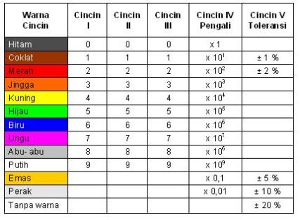
Untuk resistor jenis carbon maupun metalfilm biasanya digunakan kode-kode warna sebagai petunjuk besarnya nilai resistansi (tahanan) dari resistor. Resistor ini mempunyai bentuk seperti tabung dengan dua kaki di kiri dan kanan. Pada badannya terdapat lingkaran membentuk cincin kode warna, kode ini untuk mengetahui besar resistansi tanpa harus mengukur besarnya dengan ohmmeter. Kode warna tersebut adalah standar manufaktur yang dikeluarkan oleh EIA (Electronic Industries Association) seperti yang ditunjukkan pada tabel 1.1.

 Besaran resistansi suatu resistor dibaca dari posisi cincin yang paling depan ke arah cincin toleransi. Biasanya posisi cincin toleransi ini berada pada badan resistor yang paling pojok atau juga dengan lebar yang lebih menonjol, sedangkan posisi cincin yang pertama agak sedikit ke dalam. Dengan demikian pemakai sudah langsung mengetahui berapa toleransi dari resistor tersebut. Kalau kita telah bisa menentukan mana cincin yang pertama selanjutnya adalah membaca nilai resistansinya.
 Jumlah cincin yang melingkar pada resistor umumnya sesuai dengan besar toleransinya. Biasanya resistor dengan toleransi 5%, 10% atau 20% memiliki 3 cincin (tidak termasuk cincin toleransi). Tetapi resistor dengan toleransi 1% atau 2% (toleransi kecil) memiliki 4 cincin (tidak termasuk cincin toleransi). Cincin pertama dan seterusnya berturut-turut menunjukkan besar nilai satuan, dan cincin terakhir adalah faktor pengalinya.
Misalnya resistor dengan cincin kuning, violet, merah dan emas. Cincin berwarna emas adalah cincin toleransi. Dengan demikian urutan warna cincin resistor ini adalah, cincin pertama berwarna kuning, cincin kedua berwarna violet dan cincin ke tiga berwarna merah. Cincin ke empat yang berwarna emas adalah cincin toleransi. Dari tabel 1.1 diketahui jika cincin toleransi berwarna emas, berarti resistor ini memiliki toleransi 5%. Nilai resistansinya dihitung sesuai dengan urutan warnanya. Pertama yang dilakukan adalah menentukan nilai satuan dari resistor ini. Karena resistor ini resistor 5% (yang biasanya memiliki tiga cincin selain cincin toleransi), maka nilai satuannya ditentukan oleh cincin pertama dan cincin kedua. Masih dari tabel 1.1, diketahui cincin kuning nilainya = 4 dan cincin violet nilainya = 7. Jadi cincin pertama dan ke dua atau kuning dan violet berurutan, nilai satuannya adalah 47. Cincin ketiga adalah faktor pengali, dan jika warna cincinnya merah berarti faktor pengalinya adalah 100. Sehingga dengan ini diketahui nilai resistansi resistor tersebut adalah nilai satuan x faktor pengali atau 47 x 100 = 4700 Ohm = 4,7K Ohm (pada rangkaian elektronika biasanya di tulis 4K7 Ohm) dan toleransinya adalah + 5%. Arti dari toleransi itu sendiri adalah batasan nilai resistansi minimum dan maksimum yang di miliki oleh resistor tersebut. Jadi nilai sebenarnya dari resistor 4,7k Ohm + 5% adalah :
4700 x 5% = 235
Jadi,
Rmaksimum = 4700 + 235 = 4935 Ohm
Rminimum = 4700 – 235 = 4465 Ohm
Apabila resistor di atas di ukur dengan menggunakan ohmmeter dan nilainya berada pada rentang nilai maksimum dan minimum (4465 s/d 4935) maka resistor tadi masih memenuhi standar. Nilai toleransi ini diberikan oleh pabrik pembuat resistor untuk mengantisipasi karakteristik bahan yang tidak sama antara satu resistor dengan resistor yang lainnya sehingga para desainer elektronika dapat memperkirakan faktor toleransi tersebut dalam rancangannya. Semakin kecil nilai toleransinya, semakin baik kualitas resistornya. Sehingga dipasaran resistor yang mempunyai nilai toleransi 1% (contohnya resistor metalfilm) jauh lebih mahal dibandingkan resistor yang mempunyai toleransi 5% (resistor carbon)
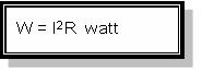
Spesifikasi lain yang perlu diperhatikan dalam memilih resistor pada suatu rancangan selain besar resistansi adalah besar watt-nya atau daya maksimum yang mampu ditahan oleh resistor. Karena resistor bekerja dengan di aliri arus listrik, maka akan terjadi disipasi daya berupa panas sebesar :
Semakin besar ukuran fisik suatu resistor, bisa menunjukkan semakin besar kemampuan disipasi daya resistor tersebut. Umumnya di pasar tersedia ukuran 1/8, 1/4, 1/2, 1, 2, 5, 10 dan 20 watt. Resistor yang memiliki disipasi daya maksimum 5, 10 dan 20 watt umumnya berbentuk balok memanjang persegi empat berwarna putih, namun ada juga yang berbentuk silinder dan biasanya untuk resistor ukuran besar ini nilai resistansi di cetak langsung dibadannya tidak berbentuk cincin-cincin warna, misalnya 100Ω5W atau 1KΩ10W.
Dilihat dari fungsinya, resistor dapat dibagi menjadi :
- Resistor Tetap (Fixed Resistor)
Yaitu resistor yang nilainya tidak dapat berubah, jadi selalu tetap (konstan). Resistor ini biasanya dibuat dari nikelin atau karbon. Berfungsi sebagai pembagi tegangan, mengatur atau membatasi arus pada suatu rangkaian serta memperbesar dan memperkecil tegangan.
- Resistor Tidak Tetap (variable resistor)
Yaitu resistor yang nilainya dapat berubah-ubah dengan jalan menggeser atau memutar toggle pada alat tersebut, sehingga nilai resistor dapat kita tetapkan sesuai dengan kebutuhan. Berfungsi sebagai pengatur volume (mengatur besar kecilnya arus), tone control pada sound system, pengatur tinggi rendahnya nada (bass/treble) serta berfungsi sebagai pembagi tegangan arus dan tegangan.
NTC (Negative Temperature Coefficient), yaitu resistor yang nilainya akan bertambah kecil bila terkena suhu panas. Sedangkan PTC (Positive Temperature Coefficient), yaitu resistor yang nilainya akan bertambah besar bila temperaturnya menjadi dingin.
LDR (Light Dependent Resistor) yaitu jenis resistor yang berubah hambatannya karena pengaruh cahaya. Bila terkena cahaya gelap nilai tahanannya semakin besar, sedangkan bila terkena cahaya terang nilainya menjadi semakin kecil.
Dalam praktek para desainer kadang-kadang membutuhkan resistor dengan nilai tertentu. Akan tetapi nilai resistor tersebut tidak ada di toko penjual, bahkan pabrik sendiri tidak memproduksinya. Solusi untuk mendapatkan suatu nilai resistor dengan resistansi yang unik tersebut dapat dilakukan dengan cara merangkaikan beberapa resistor sehingga didapatkan nilai resistansi yang dibutuhkan. Ada dua cara untuk merangkaikan resistor, yaitu :
<!–[if !supportLists]–>1. <!–[endif]–>Cara Serial
<!–[if !supportLists]–>2. <!–[endif]–>cara Paralel
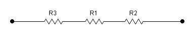
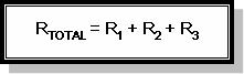
Rangkaian resistor secara serial akan mengakibatkan nilai resistansi total semakin besar.
Di bawah ini contoh resistor yang dirangkai secara serial.
Pada rangkaian resistor serial berlaku rumus :
Sedangkan rangkaian resistor secara paralel akan mengakibatkan nilai resistansi pengganti semakin kecil.
Di bawah ini contoh resistor yang dirangkai secara paralel
Pada rangkaian resistor paralel berlaku rumus :
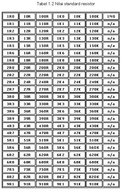
3. Nilai-nilai standar resistor
Tidak semua nilai resistansi tersedia di pasaran. Tabel 1.2 adalah contoh tabel nilai resistansi resistor standard yang beredar dipasaran. Data mengenai resistor yang ada di pasaran bisa didapat dari Data Sheet yang dikeluarkan oleh pabrik pembuat resistor.
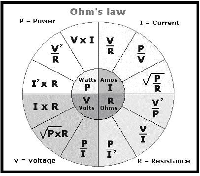
Di bawah ini beberapa rumus (Hukum Ohm) yang sering dipakai dalam perhitungan elektronika :
Di mana :
V = tegangan dengan satuan Volt
I = arus dengan satuan Ampere
R = resistansi dengan satuan Ohm
P = daya dengan satuan Watt
Konversi satuan :
1 Ohm = 1 Ω
1 K Ohm = 1 K Ω
1 M Ohm = 1 M Ω
1 K Ω = 1.000 Ω
1 M Ω = 1.000 K Ω
1 M Ω = 1.000.000 Ω
(M = Mega (106); K = Kilo (103)
 Kami menyediakan Dummy Load Berkualitas baik